
Heat transfer | Heat recovery | Energy efficiency
Gas-to-Gas Heat Recuperators
Recover exhaust heat directly into process air. Custom gas-to-gas heat exchangers with bare-tube, finned-tube or pillow-plate designs, selected for your gas streams and cleaning requirements.
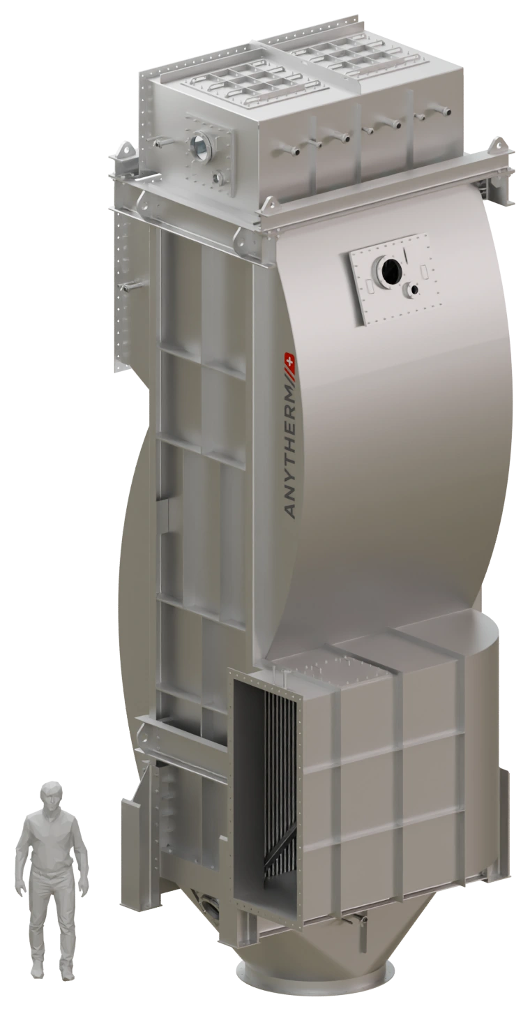
The right heat recovery concept
Direct gas-to-gas or a water loop?
Direct gas-to-gas recovery
The hot and cold gas streams pass through one unit. Heat crosses the separating metal surfaces without an intermediate water circuit. Both streams must be routed to the recuperator.
Indirect recovery via water
Separate exhaust-air recuperators and preheaters are connected by a water circuit. This can suit heat sources and users in different locations or systems with several heat sources and consumers.
Designed around your process
- Geometry adapted to dust, deposits and contamination.
- Stainless steel or higher-alloy materials selected for the media.
- Access for inspection, maintenance and cleaning.
- Integrated cleaning-in-place (CIP) where specified.
Dust loading, deposits, chemical composition and condensation influence the choice of materials and heat transfer geometry. Thermal performance, pressure loss, stream separation and cleanability are considered together.
| Parameter | Design / scope |
|---|---|
| Heat exchanger types | Bare tube, finned tube or pillow plate |
| Materials | Stainless steel or higher-alloy materials |
| Surface spacing | Adapted to the duty and contamination |
| Unit size | Custom dimensions, from small to large equipment |
| Cleaning | Maintenance access and optional CIP |
Indicative design information. Limits depend on the duty, materials and configuration and do not necessarily apply simultaneously. Final performance is confirmed for the agreed operating conditions.
Why Anytherm
Equipment engineering meets energy expertise.
Heat recovery and pinch expertise
We connect equipment selection with useful heat demand. Our analysis helps identify suitable temperature levels, operating profiles and integration opportunities.
Cleaning designed into the equipment
Surface geometry, maintenance access, drainage and CIP are considered from the start, according to the actual media.
Engineering through to delivery
We coordinate thermal and mechanical design, installation interfaces and the agreed equipment scope. Your team has a direct engineering contact.
Equipment in practice
From an early major project to a repeat order.
Two different recuperators illustrate how we adapt the equipment to the process and installation. The longstanding relationship with companies in the Kerry Group has continued with a repeat order.

Repeat order for Kerry
Approx. 800 kW · approx. 1,500 tubes · over 10,000 kg
Stainless steel construction with integrated CIP cleaning, FEM verification and CFD-supported duct design.
An early large single unit
2019 · 30,000 kg · bare-tube design · integrated CIP
Delivered to a company now part of the Kerry Group. The view shows the inlet arrangement and the first visible tube rows.
The details behind reliable operation
Tube layout, access, cleaning connections and duct geometry are part of the same engineering task. The Kerry project gives a closer view of manufacturing, integrated CIP and installation.
More reference projects
More project references: integrated units and recuperators.
Gas-to-gas heat recovery can also form part of a complete air intake unit. The examples from Germany and Finland show this integrated approach. Further exhaust-air and flue-gas recuperators illustrate the breadth of our heat recovery equipment.
Germany
Air intake unit with integrated gas-to-gas heat recovery and CIP
Finland
Air intake unit with integrated gas-to-gas heat recovery
Netherlands
Exhaust-air recuperator with condensation heat recovery
Germany
Flue-gas recuperator unit
Denmark
Exhaust-air recuperator
Before equipment selection
Find the best use for recovered heat.
A heat recovery or pinch analysis matches available sources with demand at suitable temperature levels. Operating hours, useful recovered energy, energy prices and installation costs determine the economics. We assess payback for the actual project rather than treating exchanger capacity as annual savings.
Practical questions
Can contaminated gas streams be used?
Yes, where materials, spacing and cleaning can be matched to the media. Please share the gas composition, dust or deposit characteristics and cleaning requirements so we can assess the duty.
Can condensation heat also be recovered?
For suitable processes, cooling below the condensation temperature can recover additional heat. Materials, drainage, corrosion and cleaning requirements must be considered in the design.
Which information helps with an enquiry?
Useful starting points are gas or air mass flow, inlet and target temperatures, operating hours, contamination, permissible pressure losses and the available installation space. Preliminary values are welcome.
Let’s talk about your process
Discuss your project with our engineering team.
Share your process, operating conditions and what you want to improve. A complete specification is not needed to start a conversation.
[email protected]
+41 78 722 2200
Your heat recovery specialist: Tobias Helbling, Head of Industrial Energy and Heat Recovery.